

Key Parameters Affecting Surface Roughness in Machining
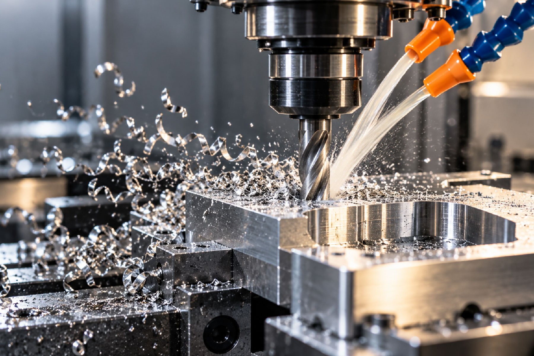
❝Explore the concept of surface roughness determining part quality in machining and the key manufacturing parameters affecting it.
Surface quality of manufactured parts in machining processes is a critical quality criterion that directly affects part life, assembly fit, and mechanical performance. Achieving the desired surface roughness value in operations performed on CNC sliding head lathes and conventional machines requires the coordinated control of many different parameters. To minimize error rates in production processes and maintain standards, a detailed examination of the core factors influencing surface quality is essential.
The Relationship Between Cutting Speed and Surface Quality
Cutting speed is one of the most dynamic factors determining surface roughness in chip removal operations. As the movement speed of the cutting edge over the workpiece surface increases, it is generally possible to achieve cleaner and smoother surfaces. At low cutting speeds, the material tends to tear away, which can lead to microscopic roughness and burrs.
Higher cutting speeds contribute positively to surface quality by reducing built-up edge formation. However, cutting speed must be optimized in accordance with machine capacity, tool geometry, and workpiece material properties. Excessively high speeds can accelerate tool wear, negatively impacting surface quality over time.
The Impact of Feed Rate on Surface Roughness
The rate of tool advance along the workpiece axis (feed rate) leaves a direct mechanical mark on the surface roughness profile. Theoretically, surface roughness is a mathematical combination of the cutting insert's nose radius and the feed rate.
- As the feed rate decreases, the depth of the marks per tooth is reduced, resulting in a smoother surface.
- Increasing the feed rate shortens production time but leaves more prominent feed marks on the surface.
- In precision machining applications, feed rate must be selected by balancing tolerance limits and surface roughness requirements.
Cutting Tool Geometry and Nose Radius
The design of the cutting tool, the form of the cutting edge, and the nose radius are other fundamental elements determining surface quality. The nose radius ($r_{\epsilon}$) on the tool tip directly affects the height of the peaks remaining on the machined surface.
Cutters with a larger nose radius distribute the marks on the surface, allowing lower roughness values to be achieved. However, larger nose radii can increase radial cutting forces and trigger the risk of vibration. Therefore, correct tool selection must be made by taking workpiece rigidity and machine dynamics into account.
The Role of Vibration and Machine Dynamics
Vibrations occurring during machining are among the greatest obstacles disrupting surface roughness. A lack of rigidity in the machine, workpiece, or cutting tool causes oscillations known as chatter in the cutting zone.
These oscillations leave wavy and irregular marks on the surface, bringing dimensional and form errors along with them. To prevent vibration:
- Proper clamping techniques and suitable tool holders must be used.
- Cutting parameters should be kept within the dynamic limits of the machine.
- Worn or unbalanced tools must be replaced in a timely manner.
Coolant Application and Chip Evacuation
Proper coolant application removes heat from the cutting zone, extending tool life and indirectly supporting surface quality. At the same time, rapid evacuation of chips from the cutting zone prevents chips from re-hitting the workpiece surface and causing scratches.
High-pressure coolant systems play a significant role in maintaining surface integrity by facilitating chip breakage, especially when machining difficult-to-cut materials.